Simple CAD inside IntelliG-Code!
When I started this software I had no idea I would ever get this far, but a year into it and I think it's become just an awesome tool at this point. I never had the intention to build a CAD interface but I must say I think it was worth it.
First lets understand that for simple things I hate having to draw. It's way too much work to open a CAD program draw something export it and then import it into a CAM software where I have to define paths for every line and then export the gcode to finally send it to the machine.
The GOAL of IntelliG-Code was to eliminate drawing /export/ import/define paths/export again and run. And I think I pretty much did that in more ways then I had ever envisioned. Are there settings that you have to tweak each time to do something? sure but they are small simple and you have to define them anyways regardless of what CAD CAM process you go with. I wanted things to be so simple a caveman could do it, well almost.
So why CAD if you don't like drawing? Umm... Because CAD means Computer Aided Drawing or Design depending on whom you ask, but this CAD is not really like drawing at all, the computer does all that for you. It's about time you don't need a degree in the cartesian coordinate system to get something simple done. And that was my inspiration to build this add on.
Now to how it works and what to expect. To open it simple go to Windows -> SimpleCAD
You will get something like this
:
*One quick note as of this moment all dimensions are in INCHES, but support for MM may come some day
**Another note as of this document the (0,0) point is ALWAYS the lower left of the grid, no CENTER point is supported YET.
So on this screen you enter your material width and height in inches, you enter how often you see a grid line which in this case is every 1/2 inches, and how accurate the snap points are which happens to me 1/8 of an inch default but feel free to put another decimal in there.
Then you create the canvas and you get this screen:
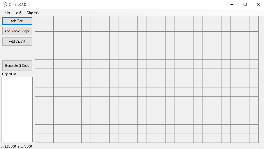
At this point you can see that there are no drawing tools, so what good is it? And that is where I say it's AWESOME, I cant draw well even with a computer so who needs drawing tools! No seriously this was made with the intention of making simple signs easy to make, not to build automotive parts. After all if you need a specific part built you WILL need exact drawing measurements and lots of work will be required. This tool is really a super fast way to make ART and Signs. No need to draw here it's all drag and drop baby!
So lets say we want to make an ellipse cut out sign. Something simple and just looks nice somewhere on a wall. We can start by drawing the ellipse, to do this click the Add Simple Shape button and you get this screen:
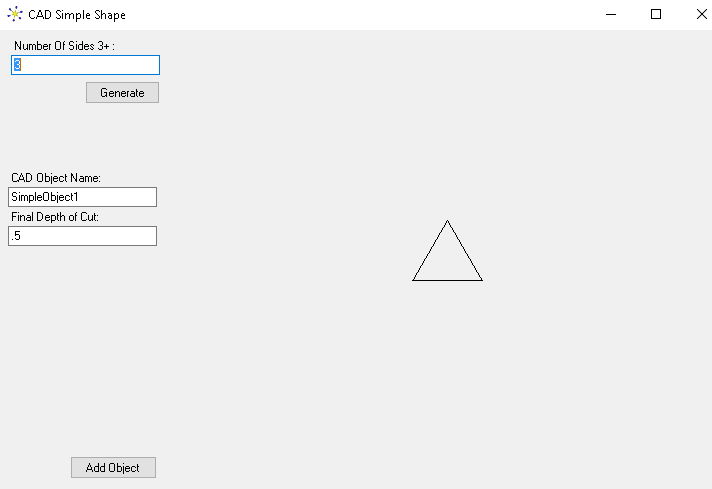
Now this is super simple if you want a Triangle, Square, Hexagon, or any shape with a number of sides to it. Try it out, you simply type the number of sides and click Generate and it makes that shape! So easy! So now you are asking that's great where is the ellipse? Well that's easy just make the number of sides about 3000 and you got it!
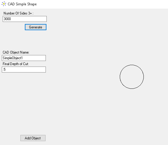
You say that's a circle where is the ellipse? No worries... Just name the shape EllipseCutOut and set your final depth to your liking and click Add Object.
At that point you can reshape and resize all you want with the 4 corners, stretch it out and it's an ellipse!
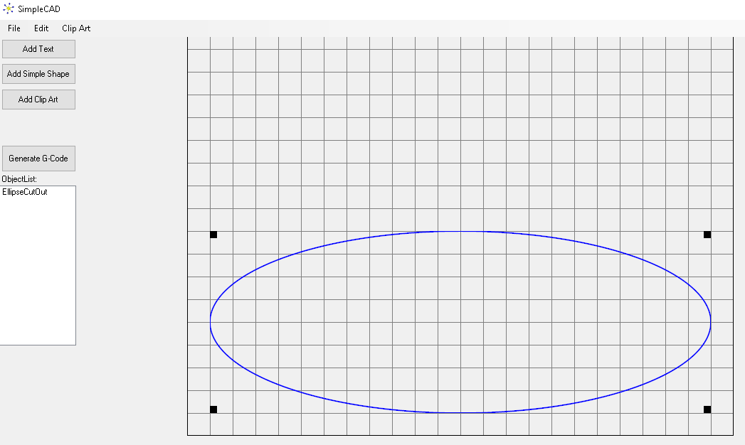
You will note that on the left there is a list of Objects so make sure you name them and that box actually has a use but may have more uses as well in the future. What is the use of that list currently? It's the only way to Un-Set an object from being "Set as Background" Speaking of which how and why would you want to do that?
Well this is a great example of why you would do that. Because this CAD works as drag and drop objects instead of drawing it, they can become layered, and they can be moved around by dragging which means you might accidentally click the back one and drag it around by accident. So to eliminate that issue right click on the object and you get this awesome menu:

So there are some cool things here. First yes you can rotate any way you want, you can also mirror X or Y but then there are these other things... Send to Back basically sends this layer back so you can get to another object. Show Center Lines draws dotted lines through the center and around all 4 edges so you can make centering another object on top of this one very easy. Locked in place prevents you from dragging the object HOWEVER, you can still re-size with the 4 corners and it can still be layered which is why I built the Set As Background. Once set as Background, it is like part of the canvas and it no longer can be moved, right clicked, or anything else. So once you go that route you need the object list box to un-set it. To un-set the background image left click it on the list box and then right click and choose Unset Background.

Simple and effective.. The Duplicate is a form of copy and paste to get another one, the Reset Aspect ratio is just that it sets the aspect exactly to the same as when it was first put on the canvas.. One caveat is that if you rotate then resize the image then rotate it back and then reset the aspect ratio, it's not going to fix the SKEW that you caused by re-sizing a rotated object.
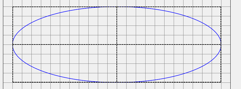
Ok so before I set it as background I set the show center lines so I could line up my text. If you are following along sorry, you may need to Unset background then set your center lines then set as background..
This is what you get at that point:
Not lets add some text, here is the text box:
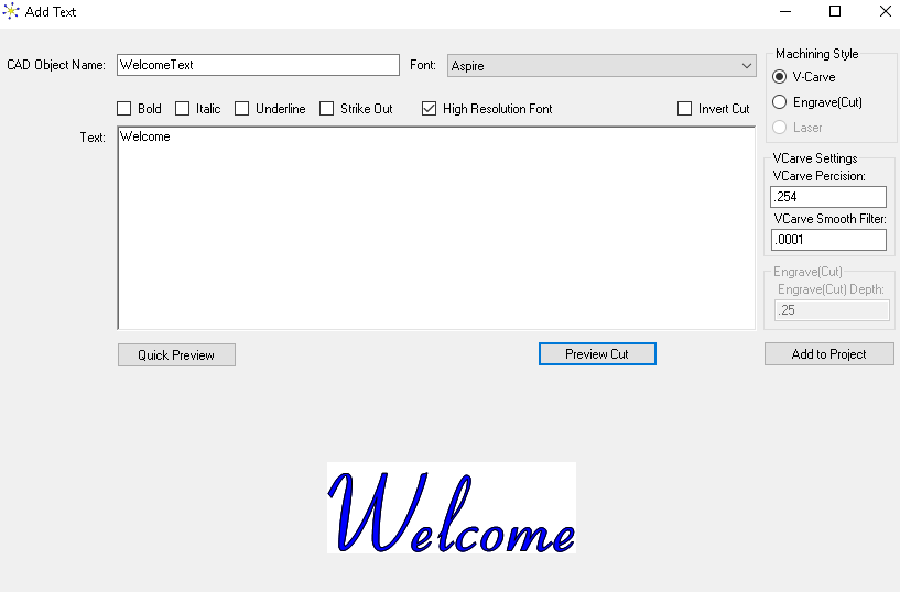
Ok you will notice this is super simple also! Just choose a font (not all work well for V-Carve which is why I built a preview cut option) but most work just fine. When you click preview cut the BLUE areas are what gets CUT. So make sure they are Inside, unless you want the letters to stick out in which case you want the blue OUTSIDE. Either way there is an Invert box to make it witch ever way you want. If you notice a large blue circle sticking out of a letter somewhere then you probably need to find another font because that means the font has something funny with the way it was drawn and it cant carve that. There is a smooth factor and precision factor, you can leave those alone. You could make it more perceive to .1 but any thing smaller will make generating the paths a VERY LONG task.
You will notice it also has Engrave, this will simply draw the outline, and Laser will come soon. So lets add the text and center it. Here you can see I also set the show center lines and lined them up:
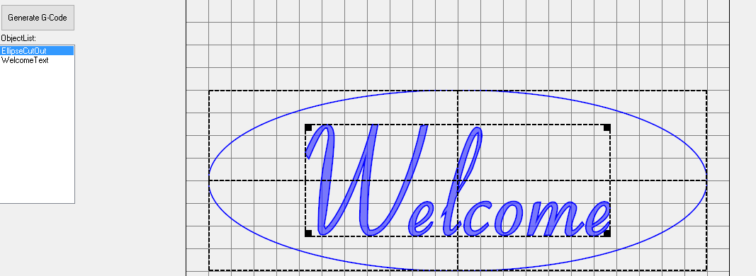
Ok so I'm pretty much done. A couple of things to think about. Your V-Carve bit will need to be WIDE enough to make the cut, if it is not you will end up with an outline of the text. Since my grid is .5 inches and my V-Bit happens also to be .5 inches you can glance at the widest part of the text in this case the large W on the left edge and see that my bit can easily plunge deep enough to make the width of the letters.
So how large is this welcome sign? Well I started at the .5" mark and ended just before the .5" mark on a 12" grid making it 11" wide. The top of the ellipse is at 4.5" and the bottom is at the .5" mark so it's 4" tall.
Here you can see I un-set the center lines and I think it looks great:
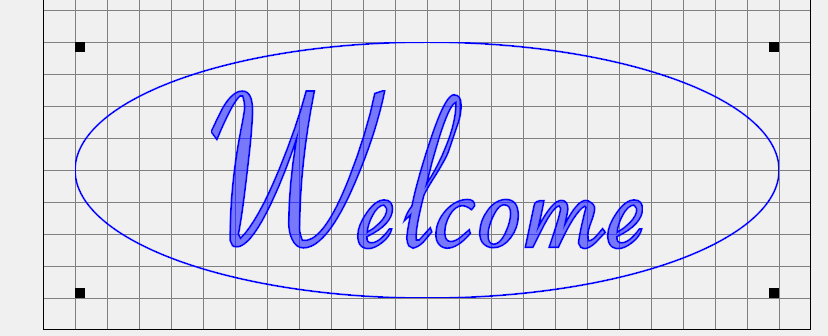
Some people worry about aspect ratio, but honestly what you should be concerned about is what looks good! If you think it looks good then go with it, there is no requirement with ART to make things be an exact aspect ratio.
So lets talk about how to machine this. First lets mention you can save and load the projects from the file menu. When you load it, it will automatically set the canvas size and grid size as the original. Ok to machine this click the Generate G-Code button and you get this screen:
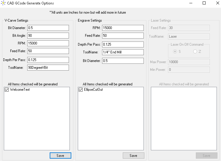
Ok here you set your V-Bit settings and save. You will notice that the Ellipse is in the Engrave section this is because it simply follows the path there is no V-Carve calculations required. You can V-Carve the text and then use a flat bit to cut the ellipse out. Each can be saved and added to a project directory. You can add a pause in between so you can change your bit and you are good to go. You can Uncheck anything you do not want to generate paths for. This allows you to say engrave a clip art with a V-Bit in the engrave section and then uncheck the cut out part. Then you can generate just the cut out part separately. I hope you get the idea there.
Ok that's it for the first part I'll talk about clip art in the next one! You can see in less then 10 minutes you can make a beautiful sign with this CAD like software. And stay tuned because there are more features to come!